The four wheels of the axis are the same, and the anchor is the translation vector of each wheel.

Set the anchor and axis in HingeJoint->jointParameters, where axis indicates which axis of the wheel to rotate around, and anchor indicates the position around the rotation vector. For each wheel, if this parameter is not used, the phenomenon that the robot's wheels will "fly away" will occur. Step9: The last step is also the most important step. Here we also need to set the name (name) in the RotationalMotor parameters of the front left, front right, rear left, and rear right to: wheel1 wheel2 wheel3 wheel4, this is us To prepare for our later establishment of the controller, because we set the speed of the motor in the controller, we need to access each motor through this name and set the speed of the motor. (You can directly select HingeJoint and then use Ctrl+C and Ctrl+V) Step8: Repeat this four times to create the remaining four wheels, and then name the four wheels respectively. (The color of the wheels can be modified in the shap defined in step5) Define this HingeJoint macro as "WHEEL1" so that we have created a new wheel. The displacement transformation of the first wheel is set to (translation x=0.06 y=0 z=0.08), and the rotation transformation is set to (rotation x=0 y=0 z) =1 angle= 1.57 rad). Step7: Finally, we set the displacement transformation and rotation transformation of the wheel. Step6: Set the boundingObject property in the node HingeJoint->endPoint to the Wheel shape we just defined macro, and set the physics property, and define the physical property macro as physics_wheel After setting this, set this The shape macro defines "Wheel". Step 5: For the newly added "solid", add a " Shape " node to the "children" property to set the appearance and geometric properties (the geometric property is a cylinder), set the radius to 0.03 and the height to 0.02. Step 4: Add a " HingeJoint " node to the "children" attribute of the robot variable model, and set the jointParameters attribute of the HingeJoint node, and then set the device attribute to RotationalMotor), add a "solid" node to the endPoints attribute Step 3 : Define the Shape node macro as Body, and set the Robot ’s boundingObject property to the just defined Body, and finally set Physics properties of Robot. Set the length, width and height of the external geometry parameters to (X=0.1 Y=0.02 Z=0.5),

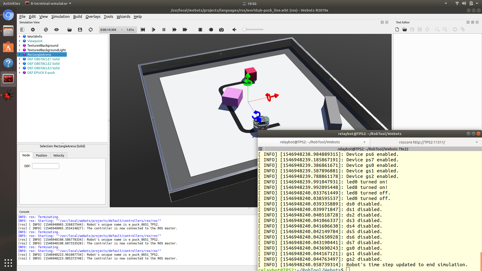
Here we can modify the color of the cube by modifying the appearance parameters of shape. So that you can See that there is an extra cube in the environment. STEP 2 : a robot variables in the model "children" add a "shape" node attribute, and set the appearance attributes of the shape node and a geometry attribute, wherein geometry attribute is set to box We will create a four-wheeled car model on this basis. This model already contains an e-puck robot model. Here I opened a "e-puck_line.wbt" world model. Next, we will build a four-wheeled trolley model in webots step by step.įirst of all, let's open an environment model. The following picture shows the effect of the trolley created by our blog.


 0 kommentar(er)
